
Electrician Circuit Diagrams
Electrician Circuit Diagrams
When doing electrical work, especially starting off or installing difficult/unfamiliar fixtures, it is recommended to follow a wiring diagram. There are different types of wiring diagrams that you may encounter while installing certain appliances, like a furnace. But, for this course, we will be using what is called a “circuit diagram.”
In a circuit diagram, each component is shown with a graphical representation of that component. This helps simplify installations because you do not need to try to interpret a schematic to understand the circuit. The part in front of you looks just like (or very similar) to the part that is on the circuit diagram. These diagrams are also useful because they show how the wires are connected to the components themselves.
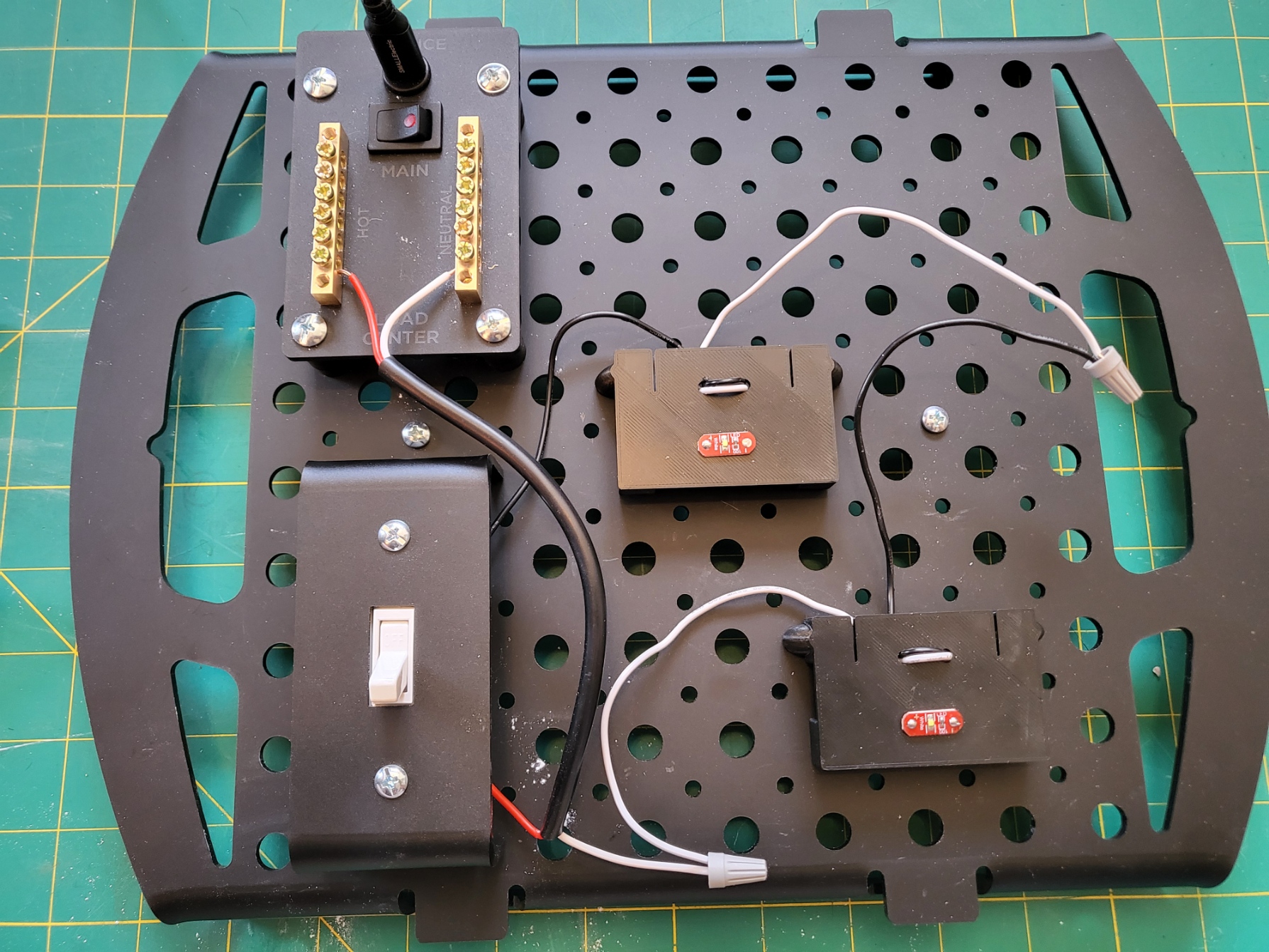
Below is a circuit diagram of the series circuit you made at the end of Lesson 5, with a picture of the actual circuit below that! Note: because of the difficulty of seeing the white wires on a white background, the white, neutral wires have been replaced by purple wires instead.
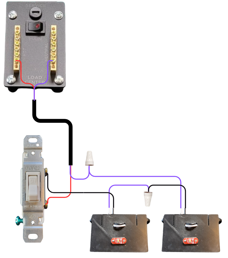
In this course, the size of the WorkBench makes it easier to accurately represent the length of wires and cables in the circuit diagram. When working on actual circuits, the cable length between junction boxes is significantly shortened even if the two components are across a room. Double-check runs of cable to avoid costly waste!