Building The Lower Arm Subassembly B
In this section, you will be using the revolving joint assembly method to create the lower arm subassembly B. The servo for this subassembly functions as the robot's elbow.
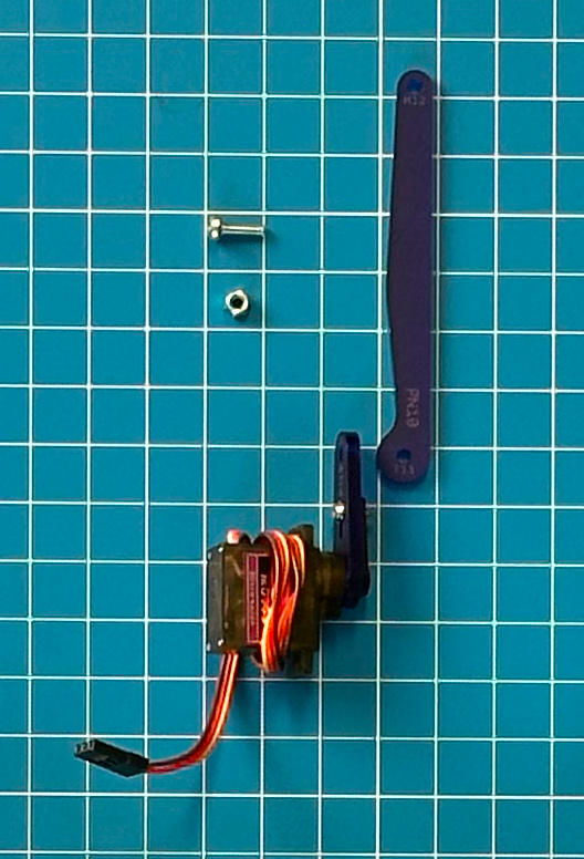
Parts and Hardware
Find the following parts and hardware:
- PN9 – Left Servo Crank Arm (with preinstalled servo)
- PN10 – Left Servo Main Link
- One M3x10mm screw
- One Nyloc nut
Reminder!
With pre-assembled components, DO NOT TURN THE SERVO or THE ATTACHED PARTS UNLESS OR UNTIL THE INSTRUCTIONS TELL YOU TO DO SO.
You might break or damage the servos if you turn the parts too far. Adjust the parts as little as possible when necessary for the installation.
Revolving Joint Assembly Method
This subassembly uses a different assembly method that we are calling the Revolving Joint Assembly Method. Because this is a joint that has to revolve, or turn, you need to make sure to build it in a way that allows the part to freely turn. Take a look at the instructions below for guidance:
- Start by preloading your screw into the plate you want to attach.
- Add on the plate you are attaching.
- Add a nyloc nut to the end of the screw and finger tighten.
- Use the wrench to continue tightening the screw until the plates can't move side to side but they can still turn easily.
- You should be able to turn the screw and nut easily using only two fingers.
Again, don't worry if this doesn't make sense yet because you will be getting practice during this step!
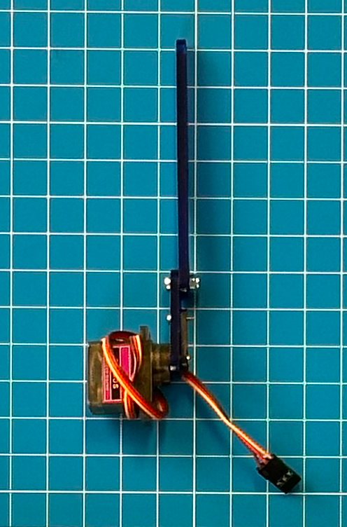
Building the Lower Arm Subassembly B
Follow these steps to complete the subassembly:
- Lay out the two parts with the servo on the side closer to you and the wire and arm facing forward. PN10 should be readable and the notch should be facing left.
- Attach The Left Servo Main Link (PN10) to the Left Servo Crank Arm (PN9) at joint #11 using the revolving joint assembly technique. Make sure not to overtighten.
- Tighten the screw gently until it bottoms out, then back it off by about a quarter turn.
- Make sure you can easily rotate the screw with only two fingers with light resistance.
- Check that PN10 is attached to PN9 on the same side as the black servo horn. You should be able to see the labels of both PN9 and PN10 on the side that is facing you. Pay close attention to how joint #11 is assembled. This one is trickier than many of the others.